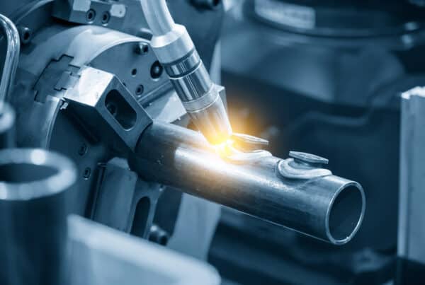
Pipe and pipeline welding is divided into many worlds. At one end is the roughneck world of owner/operator welding subcontractors. These welders wear pancake-style welding helmets, drive trucks featuring prominently mounted pipe welding power supplies on the back, and have a seemingly endless supply of welding rods tucked about their persons and vehicles. At the other end is the considerably more precise and exacting world of orbital welding. At first glance, the latter has about as much in common with the former as rocket science, DNA analysis, and other trades that involve lab coats. A closer look reveals that’s not true.
In fact, whether pipes are being welded manually or by automated machinery, the fundamentals of pipe welding aren’t actually all that different. Orbital welding joint preparation begins the same way that manual SMAW or MIG pipe welding joint preparation begins: with a side grinder. However, orbital pipe welding joint preparation gets both more sophisticated and easier from there.
Basic Pipe Welding Joint Preparation
Regardless of the process to be used, pipe welding—and all welding for that matter—begins with the removal of paint, rust, grease, anodizing, mill coat, and any other foreign materials that could compromise the weld from the surfaces to be welded. The tool that is most often used for this is a grinder. It can easily and quickly strip foreign contaminants and coatings from a pipe, leaving just the bare metal surface to be welded. A blast from an air compressor or a quick-evaporating solvent can remove metal fragments and dust left by the grinding wheel.
Care should be taken when doing the initial preparation of the joint not to damage the pipe. Grinding for too great a length of time may create a very clean and smooth surface, but it can also remove too much material and, as a result, change the diameter and dimensions of the pipe. Grinding in any single spot for too long can also cause the pipe to overheat and discolor. Altering the pipe’s dimensions or its mechanical properties through overheating affects a pipe section’s overall integrity, making it unsuitable for use in a pipeline. A basic visual inspection should be performed after initial prep to ensure that preparation hasn’t damaged the pipe. Once it has been cleaned and inspected, the pipe end is ready to be machined.
Machining Pipe Ends for Basic Orbital Welding Joint Preparation
Welds should penetrate all the way through a joint and turn two pieces of metal into a single continuous piece. When working with thick pieces of metal, it is necessary to create a groove so the weld head can reach into the depth of the joint and a contiguous weld can be laid from the interior edge of the pipe to the external surface. This groove is made by cutting an angle into the face of the pipe end on either side of the joint. In any type of pipe with a wall thickness greater than 1/8 of an inch (about three millimeters (mm)), it can be assumed that a bevel of some sort will be needed to ensure the weld can penetrate through the entire thickness of the pipe wall.
A typical manual welded bevel consist of three separate planes machined into the pipe end as shown in the diagram below:

- Bevel: A flat plane angled away from the interior diameter of the pipe and from the joint. The bevel opens up the joint so that the inside diameter is open to being welded.
- Face: A flat surface perpendicular to the pipe near the inside diameter of the pipe. It is also mirrored by a perpendicular surface on the pipe end that it will be joining.
- Counterbore: An optional additional bevel on the inside diameter of the pipe that helps to bring the width of the face within weldable dimensions, or which provides a place for interior diameter pipe welding.
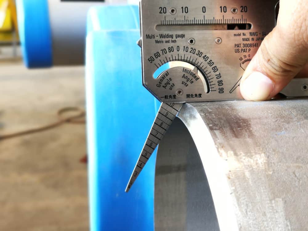
The type of bevel shown in the diagram above is called a v-groove. The total exterior angle of the weld from the outer edge of each bevel ranges from 60 to 75 degrees (37.5 degrees per side is very common in the industry, as shown in the photo below). It can be thought of as the standard pipe end preparation and can be used on pipe wall thicknesses from about 3/16 of an inch or around 4.76 mm all the way up to 1.5 inches or 38 mm. The majority of pipe end butt joints can be prepared this way before welding.
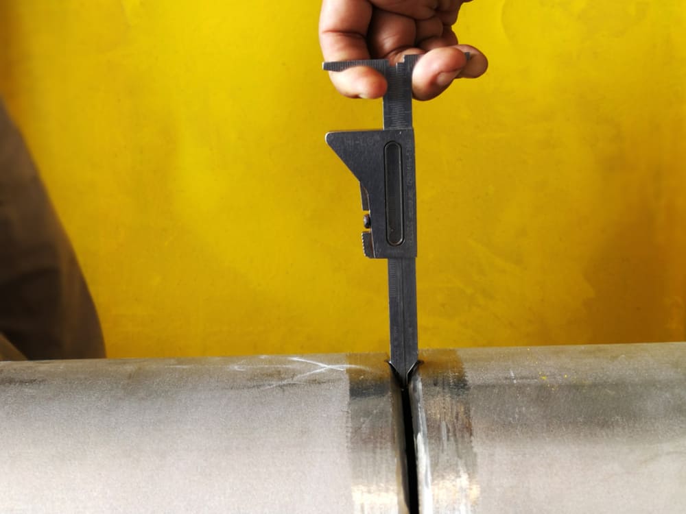
Another important dimension for pipe preparation and fit-up is the root gap, which is the distance between the opposing faces of the pipe. In most orbital welding applications, it is preferred to have no root gap and the faces are butted together in a “butt joint” configuration.
A multitude of different pipe welding best practices give exacting specifics and detail to help welders determine the proper bevel angle, thickness of the face surface, depth and angle of the counterbore, and overall geometry of pipe end preparation. These recommendations should be included in the welding production schedule, and, before welding, the prepared pipe ends should be checked against the schedule to ensure they are correct.
While single v-groove joint preparations are common, they aren’t the only type of welding joint preparation. Given the thicker materials that orbital welding often deals with, mechanized pipe welding processes will frequently require other types of joint preparation.
Pipe End Machining for Narrow Groove Orbital Welding
At pipe wall thicknesses of around one inch, the total width of the joint from the outer edge of each bevel in a single v-groove bevel starts becoming impractical to fill in, in terms of both the time and material needed.
One pipe end preparation that can reduce the volume of material needed is a j-groove preparation. It has the additional advantage of providing a flatter seat for the root pass, and it makes a narrower gap between pipe faces possible. This type of pipe preparation gets its name from the small curve at the base of the bevel. A profile of this j-groove type pipe end preparation follows:

A j-groove can also be done with two angles, which is referred to as a compound bevel, shown below:

The type of pipe end preparation and the exact angles used will depend heavily on the project requirements, thickness of the materials, and type of orbital welding process. Today’s exacting standards and high pressures also mean these bevels must be precise to avoid cracking and other issues. Once the pipe ends have been machined, they will need to be checked to ensure that the bevel angles are correct and the face is exactly the right width.
Ideally, machining pipe ends is done with specialized cutting and machining tools. The results are substantially more precise than using a side grinder and will take far less time. Much like the orbital welding process itself, the time savings and quality improvements that come from using the right tools for the job are well worth the added costs of the specialized equipment needed. The same is true of pipe fit-ups.
Pipe Fit-Up and Orbital Welding of the Joint
In the field, pipe sections are often dangled from the forks of a front end loader, and ropes are used to pull each section of pipe into place, where they are aligned with pinch bars. Fortunately, more sophisticated methods make pipe fitting substantially quicker, easier, and capable of working with longer sections of pipe.
If orbital welding joint preparation has been properly completed, then orbital welding of the pipe is simple. The operation installs a track on the pipe, mounts a weld head to the track, performs an orbital welding machine inspection to ensure the weld head and other equipment are in good working order and the proper weld schedule is loaded on the controller, then starts the welding procedure and follows along as the weld head orbits the pipe to ensure that nothing goes wrong.
A variety of automated pipe welding processes can be used to weld a pipe joint, but tungsten inert gas (TIG) or gas tungsten arc welding (GTAW), welding produces by far the most precise and highest quality welds. Automated orbital welding opens up the possibility of making thick, contiguous pipe joints entirely out of high-quality GTAW weldments. The exacting specifications required by industrial piping and pipelines are best served by precise orbital welding joint preparation and continuous, wire-fed GTAW narrow groove orbital welding.
Arc Machines, Inc. provides industrial GTAW orbital welding equipment capable of completing welds up to 12 inches thick. Arc Machines’ orbital weld heads and power supplies are the best options for exacting orbital welding projects. For inquiries regarding products, contact sales@arcmachines.com. For service inquiries, contact service@arcmachines.com. Arc Machines welcomes the opportunity to discuss your specific needs. Contact us to arrange a meeting.