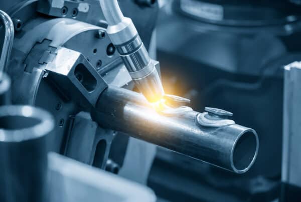
In gas tungsten arc welding (GTAW), also known as tungsten inert gas (TIG) welding, knowing the best flow rate for the inert gas is more than half the battle. It’s pretty common for inexperienced TIG welders who are having trouble maintaining adequate gas coverage to push the gas flow above recommended levels and find the resulting welds to be highly contaminated. This is due to the excessive flow creating turbulence that draws in the exterior atmosphere rather than shutting it out, drawing in not only gaseous contaminants but solid particulate matter as well, leading to porosity as well as a bad color.
The TIG welding gas flow rate is vital for producing welds that meet specifications in fabricating everyday items like kitchen equipment. In high-specification industries like semiconductors or biopharmaceuticals, typical argon gas isn’t quite pure enough for ultra-high purity pipe welding and requires additional filtration to remove moisture, and even more attention needs to be paid to purge times, gas composition, and the TIG welding gas flow rate.
Types of TIG Welding Gas
The most common type of inert gas used in any gas arc welding is argon. A 75 percent argon and 25 percent carbon dioxide blend is used in wire-fed gas metal arc welding (GMAW). Pure argon is effectively the default used for cleaner and more precise TIG welding. Applications that demand the precision of orbital welding typically don’t allow for CO2 mixes, and pure argon represents the baseline. As mentioned previously, the demands of high purity (HP) and ultra-high purity (UHP) industries mean that typical argon isn’t good enough, and they have their own standards for argon gas. These standards are:
- Oxygen content: Oxygen content needs to be less than 50 parts per billion (ppb)
- Carbon Monoxide: Carbon monoxide needs to be less than 50 ppb
- Carbon Dioxide: Levels of carbon need to be less than 50 ppb
- Total Hydrocarbons: Hydrocarbons (oils) need to be under 50 ppb
- Moisture: Contents of moisture must be under 50 ppb.
While argon represents the baseline gas for TIG welding and is by far the most commonly used, it is not the only gas used. Welding in a pure argon environment tends to produce distinctly cold-looking beads. The terminology comes from the humped look that comes from welding with heat settings too low for the purpose. In the case of TIG welded with argon, this isn’t necessarily reflective of the actual temperature of welding. It just speaks to a tendency for welds to not lay as flat as may be desired against the substrate. This can be addressed through the use of additional gases in the blend.
Helium is the first of these gases. It produces flatter welds and helps TIG welds fuse deeper quicker. However, it is an expensive gas that is also in high demand for cryogenic welds, so its use is reserved for only the most demanding applications, either as a pure gas or as a 75 percent helium/25 percent argon mix. The second gas that can be mixed with argon and used in HP and UHP welding is a bit of a shock—hydrogen.
The use of hydrogen as a shielding gas for TIG will surprise many because it is usually a contaminant. A great deal of effort is put into removing moisture and hydrocarbons from the welding environment, specifically to prevent hydrogen from contaminating a weld. Deliberately introducing it into a shielded environment may strike many as wrong. It is also not an inert gas. Hydrogen famously was what brought down the Hidenberg in a spectacular fiery fashion—so introducing it into an environment that will be intentionally struck with an open arc hotter than the sun raises eyebrows. Nevertheless, it does produce notably cleaner welds when mixed with argon in very small concentrations of 2 percent. Since it is explosive, it should not be used in welding applications with a higher than 5 percent concentration.
Purging and TIG Welding Gas Flow Rates
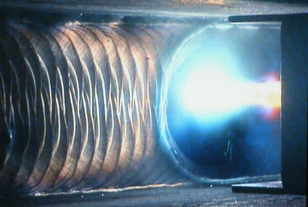
In HP or UHP welding, a clean, purified environment is almost always required. This requires surrounding the joint with an airtight environment, delivering the welding gas through a tube, and connecting fittings. In orbital welding, this requires surrounding the interior and outside of the pipe or tube to be welded around the point of union and two distinct types of purging—interior diameter purging and outer diameter purging.
Interior Diameter (ID) Purging
In interior diameter purging, the inert gas supply is routed directly into the interior of the workpiece bypassing the welding power supply and weld head. Gas flow into the area surrounding the point of union is usually restricted through the use of purge dams and other purge equipment that prevent atmospheric gases from flowing back into the area. An oxygen analyzer may be used to ensure the environment reaches the desired composition.
| Interior Diameter Purge Rate | |||
| Tube Size | ID Purge Rate(SCHF) | Purge Time(Minutes) | Restrictor Size |
| ¼ Inch | 5 | 5 | None |
| ⅜ Inch | 5 | 5 | ¼ Inch |
| ½ Inch | 15 | 5 | ¼ Inch |
| ¾ Inch | 20 | 5 | ¼ Inch |
| 1 Inch | 40 | 5 | ¼ Inch |
| 1-½ Inch | 80 | 5 | ¼ Inch |
| 2 Inch | 140 | 5 | ⅜ Inch |
| 3 Inch | 320 | 5 | ⅜ Inch |
| 4 Inch | 580 | 5 | ⅜ Inch |
| 6 Inch | 620 | 5 | ⅜ Inch |
Outer Diameter (OD) Purging
When using an enclosed weld head, an outer diameter purge is a simple matter of allowing the gas to run through the weld head before starting to weld. Following welding completion, a 30 second post purge is recommended for high-purity applications. A table of pre and post-purge times and flow rates for Arc Machines Model 8 and Model 9 weld heads can be seen below.
| Weldhead Pre and Post-Purge Guidelines | |||
| Model 9 Weldhead | Flow RateCFH | Flow RateLiters/Minute | Pre and Post Purge Time |
| 9-250 | 7-10 | 3.2-4.7 | 20 |
| 9-500 | 8-12 | 3.8-5.6 | 20 |
| 9AF-750 | 10-14 | 4.7-6.6 | 20 |
| 9AF-900 | 12-15 | 5.6-7.0 | 20 |
| 9-1500 | 15-25 | 7.0-11.8 | 20 |
| 9AF-1500 | 15-25 | 7.0-11.8 | 20 |
| 9-2500 | 25-30 | 11.8-14.1 | 30 |
| 9-3500 | 25-30 | 11.8-14.1 | 30 |
| 9-4500 | 30-40 | 14.1-18.8 | 60 |
| 9-7500 | 30-40 | 14.1-18.8 | 60 |
| E-TYPE | |||
| 9E-1500 | 25-35 | 11.8-16.5 | 30 |
| 9E-2500 | 25-40 | 11.8-18.8 | 30 |
| 9E-3500 | 30-45 | 14.1-21.2 | 30 |
| 9E-4500 | 35-50 | 16.5-23.5 | 60 |
| 9E-7500 | 40-60 | 18.8-28.2 | 60 |
| Model 8 | |||
| 8-2000 | 15-25 | 7.0-11.8 | 30 |
| 8-4000 | 15-25 | 7.0-11.8 | 30 |
The TIG welding gas flow rate for the actual TIG welding process is highly specific to the material types, the material’s thickness, and the travel speed of the weld head. The optimal gas flow rate can vary between 10 and 35 cubic feet per hour (CFH). These figures, though, serve as an upper and lower threshold, and the TIG welding gas flow rate should always be based on welding parameters and adjusted by the experience of the individual welder with the machine and application.
The gas flow will have to be such that the electrode, arc, and molten puddle cannot outpace the gas coverage, and many factors can affect this, from the airflow in the work environment to the state of maintenance of the welding machine itself. However, in either case, careful attention to pre and post-purge gas flow can provide additional support in successfully completing a weld to specification.
Arc Machines, Inc. Model 8 and 9 weldheads are long-time industry mainstays for orbital welding in aviation, pharmaceuticals, and semiconductors. We are always improving our products and advancing the art of orbital TIG welding by developing new equipment, better tungsten, and improved parameters. For more information on TIG welding gas flow rates or for sales inquiries, contact sales@arcmachines.com. For service inquiries, contact service@arcmachines.com. Contact us to arrange a meeting. Arc Machines welcomes the opportunity to discuss your specific needs.