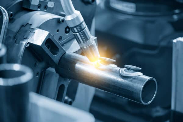
Many of the same defects common during traditional manual welding also occur during orbital welding as well. These include contaminated welds, lack of fusion, and poor formation of the weld itself. One big difference between orbital welding and manual welding is that in manual welding it is possible to compensate for some things on the fly. In orbital welding, however, material prep, joint prep, joint fit-up, and machine set up must be done precisely and correctly before welding begins. While manual welders can resolve some welding issues by changing their positioning or the way they hold the torch, orbital welding requires adjustments to the machine and these aren’t easily changed halfway through a pass.
Avoiding common orbital weld defects requires properly programming the welding controller, thoroughly preparing the welding joint, and being aware of how environmental conditions could affect the welding process. Paying careful attention to these areas not only prevents welding defects, but it can also improve welding productivity across a project or facility as a whole.
Avoiding Weld Contamination
One of the more frustrating things to discover after completing a weld is a telltale gray haze or a gritty appearance on the weld’s surface. In extreme cases, contamination of the weld can even be expressed as porosity, a group of tiny holes caused by poor gas coverage, surface contamination, high arc voltage as well as hydrogen and other gases escaping through the molten metal as it cools. Large-scale contamination, however, is generally easy to avoid.
Avoiding Porosity and Large Uneven Weld Contamination
The usual culprits for weld contamination are improperly cleaned workpieces or problems with shielding. Porosity, especially, is an indicator that a joint wasn’t cleaned well enough before welding. It is usually caused by remnants of substances like the grease used to prevent steel from rusting or an anodized coating. During welding, these substances evaporate and outgas through the weld. Porosity can be avoided by making sure that the work surface is properly cleaned and that there is no source of contamination on the joint, electrode, or fill material. Porosity and inclusions may also occur if the parent material is of poor quality with many impurities.
Avoiding Weld Graininess and Scaling
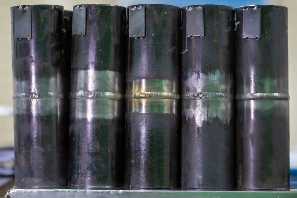
Weld contamination that takes the form of poor weld color, a fine gritty texture across the surface, or a regular, fine grain distribution across the weld’s surface means that finely structured contaminants are getting mixed in with the molten metal and forming oxides and hydroxides. The usual cause is poor shielding coverage, rather than an unclean joint or equipment. The correct gas flow rate for gas tungsten arc welding (GTAW) is 15 to 30 cubic feet per hour (cfh), or 7.08 to 14.16 liters per minute (lpm) (or a 2-to-1 ratio). Often, welders set their gas flow higher in the mistaken belief that it will make for a purer weld. Instead, it creates turbulence that pulls in contaminants. If the gas flow is set correctly, then the lines should be checked to make sure that gas can flow through them uninterrupted and the surrounding environment should be checked for air turbulence that might be disturbing the flow of shielding gas. The hoses and connections should also be checked for leaks to ensure that gas is flowing correctly from the gas source to the weld head.
Failure to thoroughly clean the joint and interrupted or impeded gas flow are the two most common causes of weld contamination. Fortunately, sources of contamination are generally easy to find, diagnose, and remove. Issues with the formation of the weld in orbital welding are generally due to not setting up the machine correctly and can be more difficult to resolve. We’ll talk about a few common problems to look out for below.
Avoiding Orbital Weld Defects Due to Amperage Settings
Many times, weld defects have to do with setting the amperage too high—welding too hot—or setting the amperage too low—welding cold. Diagnosing the cause of the problem can be difficult since both issues may have the same result of the filler metal falling out of the weld. If a welding machine is set too cold, then the substrate of the workpiece will fail to melt enough for the fill metal to bond with it. If, on the other hand, the machine is set too hot, the substrate will melt too much and lose cohesion; it and the filler metal will then fall out of the weld.
If errors in amperage setup occur in orbital welding, it is generally the result of human error or unanticipated environmental factors.
Some signs that a machine is running too hot are:
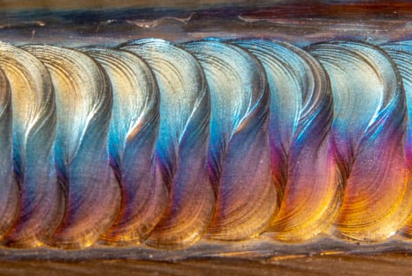
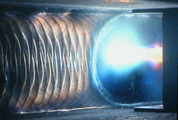
- Spattering of the metal during welding that is audible to the ear while the welding process is taking place. In orbital GTAW welding, there should be little to no spatter; audible spattering is a sign that something is wrong with either the heat or gas flow, or that the wire is not entering the puddle correctly.
- A large, visibly heat-affected zone surrounding the weld where the metal has changed color. This indicates that too much heat is entering the metal. It can also indicate that gas coverage is poor.
- A distinct flatness to the weld. The weld may also sink into the surface at the top of a pipe or tube. This occurs when the metal is too hot and too fluid, causing it to flow toward the direction of gravity. Distinctive melt patterns out of the weld towards the source of gravity in the vertical and overhead position may be another sign of a machine running too hot.
If the amperage settings of a machine are too low, the weld is running cold, or the wire feed speed is too fast for the size of the GTAW weld puddle, a welder can tell by the following indicators:
- The arc may sputter during welding as it struggles to maintain current flow across the air arc gap. This is audible to the ear, but sounds distinctly different from metal spatter.
- Metal that comes free of the weld will have a distinctive humped or circular quality as it lacks the energy needed to become fully molten and flow into or onto the surrounding surfaces.
- Welds will have a characteristic hump to them as the material fails to fully flow into the weld and remains piled above the surface.
Given the precision and hygiene demands of orbital welding, a welding production schedule is generally calculated before beginning the welding process. This makes amperage issues rarer in orbital welding than in manual welding. If errors in amperage setup occur in orbital welding, it is generally the result of human error or unanticipated environmental factors like extremes of heat or cold affecting the material prior to welding.
The first step to resolving these issues in orbital welding is to double-check the weld production schedule to ensure the correct weld schedule is being used for the material. The second step is to check the power supply for problems like loose connections that could affect current flow. Finally, if the problem is found to be due to environmental factors, then these may be compensated for by preheating the joint prior to welding, isolating from heat sources like direct sunlight, or adjusting the welding schedule to fit the environment.
Preventing Weld Cracking
When working with Inconel®, Monel®, some types of stainless steel, and other exotic alloys, cracking can occur. Welding focuses heat on one particular area, and when the base material cools it becomes less ductile and more brittle. The stress of different parts of the workpiece cooling and contracting at different rates can cause cracks in the weld or the surrounding material.
The solution is usually to preheat the welding area before welding and slowly reduce the heat after welding. This allows the material to cool down slowly without placing strain on it. In applications where precision is very important, preheating the metal surrounding a welding joint is an excellent choice even for orbital welding of forgiving materials like steel.
A weld production schedule can be used on multiple machines with multiple operators at the same time, achieving consistent results across workstations.
Perhaps the biggest advantage of orbital welding is its consistency and repeatability, which allow a weld to be repeated over and over again without creating orbital weld defects due to operator inattention or fatigue. Furthermore, once developed, a weld production schedule can be used on multiple machines with multiple operators at the same time, achieving consistent results across workstations. Developing a successful orbital weld production schedule can be compared to hiring a workforce of highly skilled and experienced welders.
One solution to using pipes and tubing made entirely from these expensive alloys is to instead use them as pipe cladding materials. This offers the corrosion-resistant advantages of these materials for a significantly lower cost. In some cases, there may be structural reasons for cladding a pipe with a different alloy than the pipe is made of—copper-clad steel, for instance, is much stronger than copper alone. In many cases, these clad pipes and the fittings that go along with them must be specially manufactured for a project. Choosing the right pipe cladding material and the correct orbital welding heads are vital for the successful completion and function of a project.
Arc Machines, Inc. has decades of experience in manufacturing orbital welding machines and developing weld schedules for the aerospace, nuclear, petrochemical, and other industries. For inquiries regarding products, contact sales@arcmachines.com. For service inquiries, contact service@arcmachines.com. Arc Machines welcomes the opportunity to discuss your specific needs. Contact us to arrange a meeting.