What ultimately defines the quality of a pipe weld is how well it meets standards. There are a bewildering variety of international, national, and industry-specific standards for pipe welding. In spite of the sheer number of these guidelines, it is entirely possible for a project to call for a weld quality beyond that of any established standards.
For example, the semiconductor industry demands cleaner and more precise welds on the pipes used in microprocessor manufacturing. This demand has driven advances in the quality attainable in pipe welding in spite of the fact that no recognized industry standard exists for pipe welding in semiconductor manufacturing.
It is impossible—and impractical—to exhaustively define pipe welding quality control practices for all nations, industries, and projects. However, by focusing on the fundamentals, it is possible to provide guidelines that project managers can use to develop best practices specific to the needs of their project. These best practices can increase welding speed, improve weld quality, reduce rejection, and ensure that completed projects meet or exceed expectations.
Developing Specifications for Pipe Welding Projects
The quality of a pipe weld begins in the design phase. This is where the pressures, loads, stresses, and other external forces that a pipe weld must be able to resist are decided. These specifications will define the dimensions of the pipe, what alloys are used for the pipe, and, by extension, how the pipe is welded. Designers will also need to reconcile the engineering needs of the project with the legal and industry standards that govern the work.
In order to do this, the designers and mechanical engineers setting the welding specifications of the pipes will need to consider factors such as:
- Materials: The materials used in pipe welding must be suited for their intended use both mechanically and chemically. The final pipe must be able to withstand the pressures of the fluids or gasses contained within as well as resist any corrosive effects.
- Joint Fitting: The weld itself must stand up to the internal pressures contained within the pipe, the load exerted by the weight of the pipe itself, and any external loads created by the structure or environment.
- Joint Preparation: In order to meet the specifications for each individual joint fitting, the piping and other materials will need to be prepared through machining or onsite grinding. Provisions for purchasing prepared materials or equipment for onsite preparation will need to be made.
- Filler: The composition of the metal or alloys that will be used in the weld will need to match the mechanical and chemical needs of the joint. The filler material may need heating or cooling to maintain the temperatures needed to form the mechanical or chemical structures required by weld specifications.
- Weld Process: Numerous different arc welding processes can be applied to pipe welding. The quality of the welds produced by these different processes varies in corrosion resistance, fusion to the base material, mechanical strength, and how clean the weld is in the interior surface of the pipe.
- Shield Gases: Different welding gases and mixed gases result in different weld results. The shielding gas used can affect the heat of the welding arc, the contour of the arc, and the resulting weld. The welding gas and gas flow needed to obtain the desired weld quality should be included in the weld specification.
All of these factors are normal considerations in any pipe welding project, and should be familiar to mechanical engineers. However, the staging, positioning, and deployment of the labor and equipment needed to weld each joint to spec are often overlooked. This frequently causes delays, and further delays may be caused if onsite personnel don’t succeed in their first attempt at a weld. Generalized, basic pipe welding quality control best practices in the design phase can prevent this scenario.
Early Implementation Is Key to Quality Control Standards
Pipe welding quality controls are specific to the engineering demands of each project. There is no single set of best practices that can cover every project, but there are fundamentals that should be considered early in the process. These will inform the development of quality control standards.
These fundamentals should take into consideration:
- Dimensions: Many issues on a pipe project can be prevented by being mindful of how much space will surround each joint. Designs should leave enough room for the work to take place. If a project’s needs demand that pipes be spaced too closely for a welder to work easily, or in an inaccessible area, then a process like automated orbital welding, that can produce quality work to spec in tight spaces, should be considered.
- Pipe Alignment: A plan for how sections of pipe will be assembled onsite and brought into the correct alignment should be developed in advance, and the tools needed to bring them into alignment and support them during welding should be part of the materials schedule. If existing tools and supports are inadequate, allowances for fabricating the required devices should be made.
- Communication: Weld schedules are a normal element of any pipe welding project. The weld schedules that are developed for a given project should clearly note any unique elements in particular joints or phases in the process.
- Process Controls: In addition to making sure all information is clear and available, a procedure should be developed to ensure that important information is shared with welders and their supervisors. A multi-step sign-off process that ensures that all parties have read and understood specifications and weld requirements should be in place before welding begins. Process controls need to be implemented starting with the purchase of the materials and consumables through the post-weld processes.
The pipe welding quality control best practices above can be applied across industries. Focusing on these fundamentals allows the development of project-specific pipe welding quality controls that not only ensure reliable welds, but also keep a project on schedule. However, these considerations are only part of the equation; it’s also important to perform testing of every critical joint.
Quality Pipe Welding Requires Testing
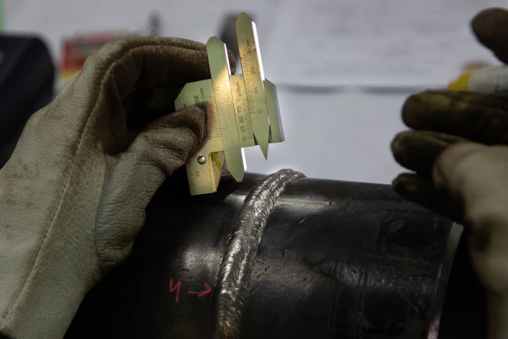
The most common way to test welds is a visual inspection. Surface weld discontinuities like cracks, porosity, and slag inclusions can be seen in the surface of the weld. Temperature irregularities that can indicate that the weld has burned too hot or that the pipe itself has been excessively heated can show up as a blue or purple color in the metal.
When conducting a visual inspection the following needs to be kept in mind:
- Proper lighting is very important in every inspection. Multispectral lights such as xenon, in color temperatures of 4000-6000 kelvin (K), are recommended over LED lighting. LED lights are monochromatic and shifted into the blue spectrum, which can hide heat discoloration and textures that indicate discontinuities.
- Lighting should be at least 350 lux. Brighter lighting of at least 500 lux is recommended for inspecting the workpiece and is the European code standard.
- The observation angle to the weld seam should be greater than 30 degrees if optics are used to conduct inspections. Too narrow an angle will interfere with detailed resolution of the weld.
- Use a reference object to check the resolution of direct and indirect inspection methods. The 1951 USAF resolution test chart is an inexpensive device that provides a way to check and calibrate optics.
Since pipe welds often involve pipes whose interior pressures are well above the surrounding atmospheric pressure, a visual examination of pipe welds generally isn’t sufficient. In order to ensure that welds can be relied upon, non-destructive testing of the following types is commonly used:
- Hydrostatic Testing: Non-compressible fluids or oils should always be used for hydrostatic testing. Gases can become compressed and may cause a weld or seam failure to explode with dangerous force. Fluids and oils should be pumped through the pipe at pressures that typically exceed the final flow through the pipe. The pipe is then inspected for leaks. If a project requires testing with pressurized gas before welds can be approved and finalized, they should be dye and x-ray tested first, and then pressurized in an evacuated area.
- Dye Penetrant Testing: A dye is sprayed onto the finished weld and then wiped away after a period of time. Any surface defects trap the dye and become visible when a developer is applied. This method has the drawback of only detecting flaws in the surface of the weld. The temperature of the workpiece should be checked against the temperature rating of the dye penetrant as the dye will not work properly on a pipe or tube that exceeds its temperature rating.
- Magnetic Particle Testing: A magnetic field passes through the weld and small magnetic particles are applied to show defects close to the surface. Only surface or near-surface defects can be detected using this method.
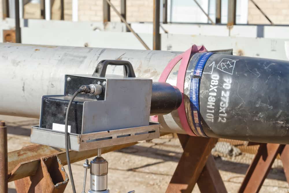
- Ultrasonic Testing: Vibrations penetrate the weld and are reflected back to the detector. Discontinuities in the material and defects are shown by changes in the reflected waves. This method can detect defects throughout most pipe welding.
- Radiographic Testing: Functionally similar to medical x-rays, this method uses x-rays or gamma rays to penetrate beneath the surface of the weld. This is a very effective method, clearly displaying defects throughout the weld.
These standard methodologies are basic to pipe welding quality control. However, best practices can be improved upon through greater attention to accountability in welding work, the methodology applied to testing, and the way that unacceptable welds are remediated.
It’s important to ensure that those working on a welding project understand what is and is not an acceptable fix for a weld that fails testing. In many industries and projects, a standard grind and replace is not remotely acceptable. It is vital to project deadlines that pipe welds can be corrected to spec the first time without delay and that criteria for weld acceptance and proper remediation of weld rejection are known to all parties in advance of testing.
Pipe Welding Quality Control Best Practices Are Procedural
In pipe welding, quality control is mainly a matter of developing a step-by-step process for each joint to be welded, tested, and accepted or rejected. It also requires developing processes to ensure that the step-by-step plan is followed.
Automation has made it easier to ensure that procedures and specifications are followed in the pipe welding process. Orbital welding automates travel speed, arc voltage control, amperage, electrode oscillation, and the addition of filler material to carry out all specifications of the welding process with a speed and consistency that manual welding cannot match. Automated orbital pipe welding heads are available in small-diameter models, which can fit into areas that the human body cannot. When pipe welding quality control practices are developed for a project, orbital GTAW welding should be considered as an option for the benefits it offers throughout the construction process.
Arc Machines Inc. specializes in high-quality GTAW orbital welding equipment. To ensure quality welds on your next pipe welding project, consider Arc Machines’ orbital weld heads and welding controllers. For inquiries regarding products, contact sales@arcmachines.com. For service inquiries, contact service@arcmachines.com. Arc Machines welcomes the opportunity to discuss your specific needs. Contact us to arrange a meeting.
